- Three-Phase Transformers Low (Port Connections)
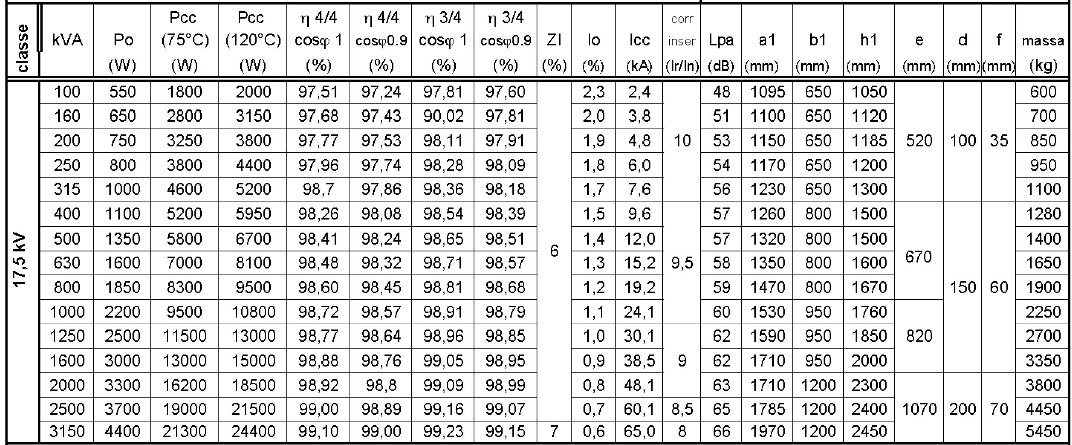
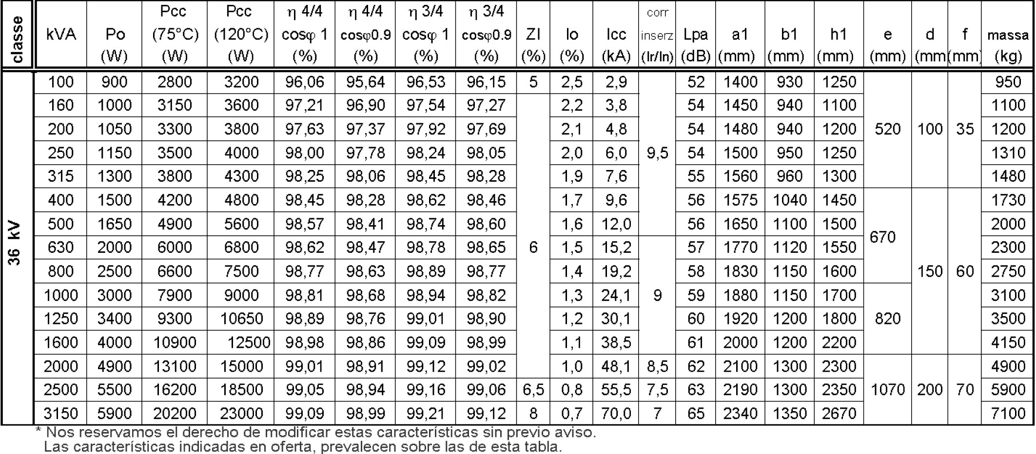
- Three-Phase Transformers Medium (Port Connections)
- Single Phase Inductors whit DC Filters – Chopper Coil
IEC-EN 60289
EC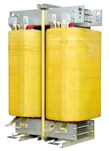 Electrical features:
- Inductance: 3.6 mH
- Rated current: 1570 Amp.
- Peak current: 2225 Amp.
- 500 Hz ripple: 300 Amp, PK/PK
- Rated operational voltage: 5300 Vcc
- Dielectric strength: 15 KV/50HZ/60 sec.
- Weight: 2850 Kgs.
APPLICATION
DC Filter (chopper coil)
* Due to the wide range available, we can offer the inductor you need on request.
- Stabilized voltage and current sources

ELECTRICAL CHARACTERISTICS :
- INPUT: 400V
- OUTPUT 1: 0 A 60 Vac – 700 Amp
- OUTPUT 2: 60 A 120 Vac – 350 Amp
- REMOTE LOCAL CONTROL
- CURRENT REGULATION
- VOLTAGE REGULATION
- RANGE 60V / 120V
- MEASUREMENTS: 1200 x 800 x 500 mm (H x W x L)
- FORCED VENTILATION
- PROTECTION: IP.20
- APPROXIMATE WEIGHT: 500 Kg
* Debido a la amplia gama existente, sobre demanda podemos ofrecer la fuente que usted desee.

- Single-phase Systems
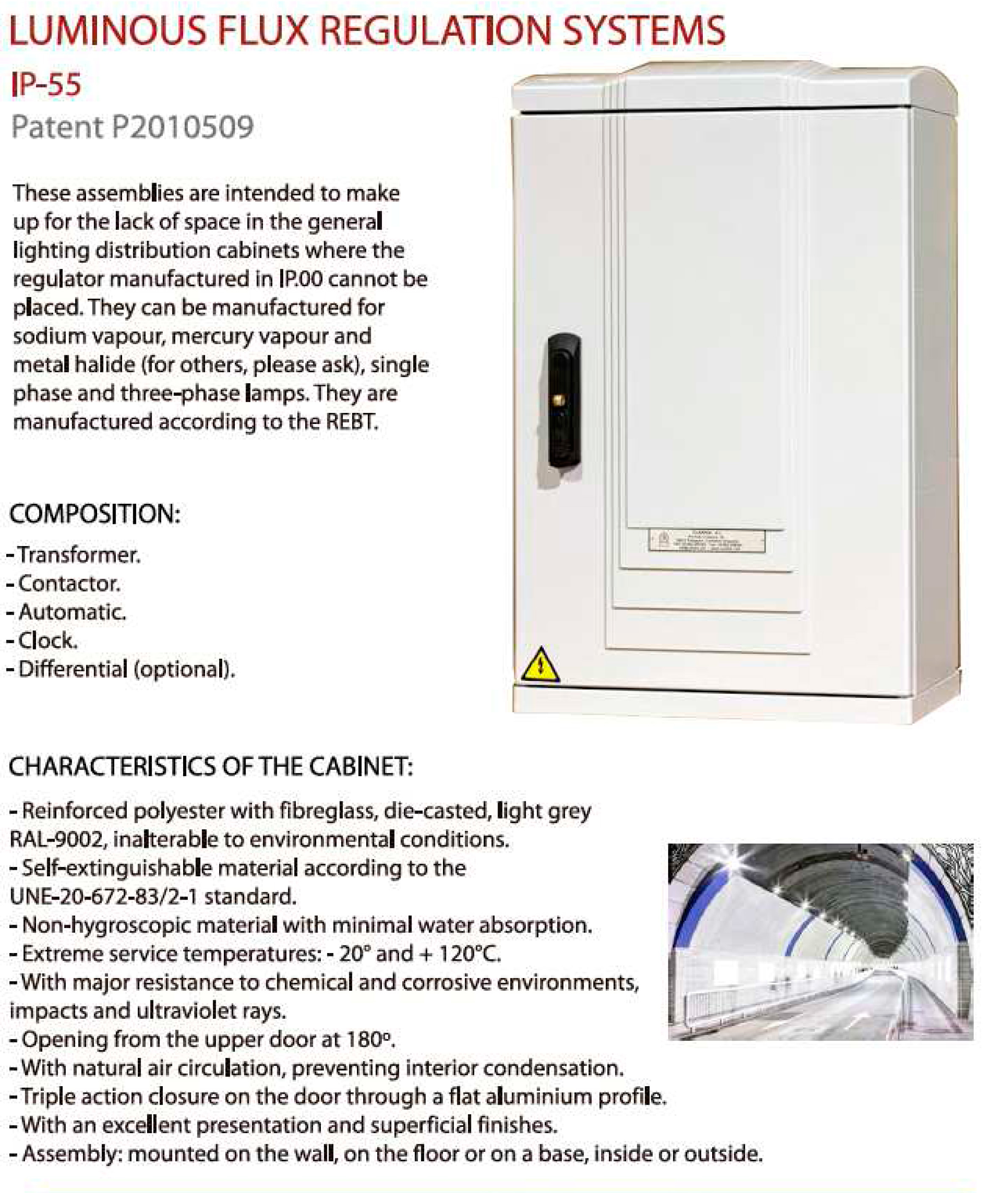
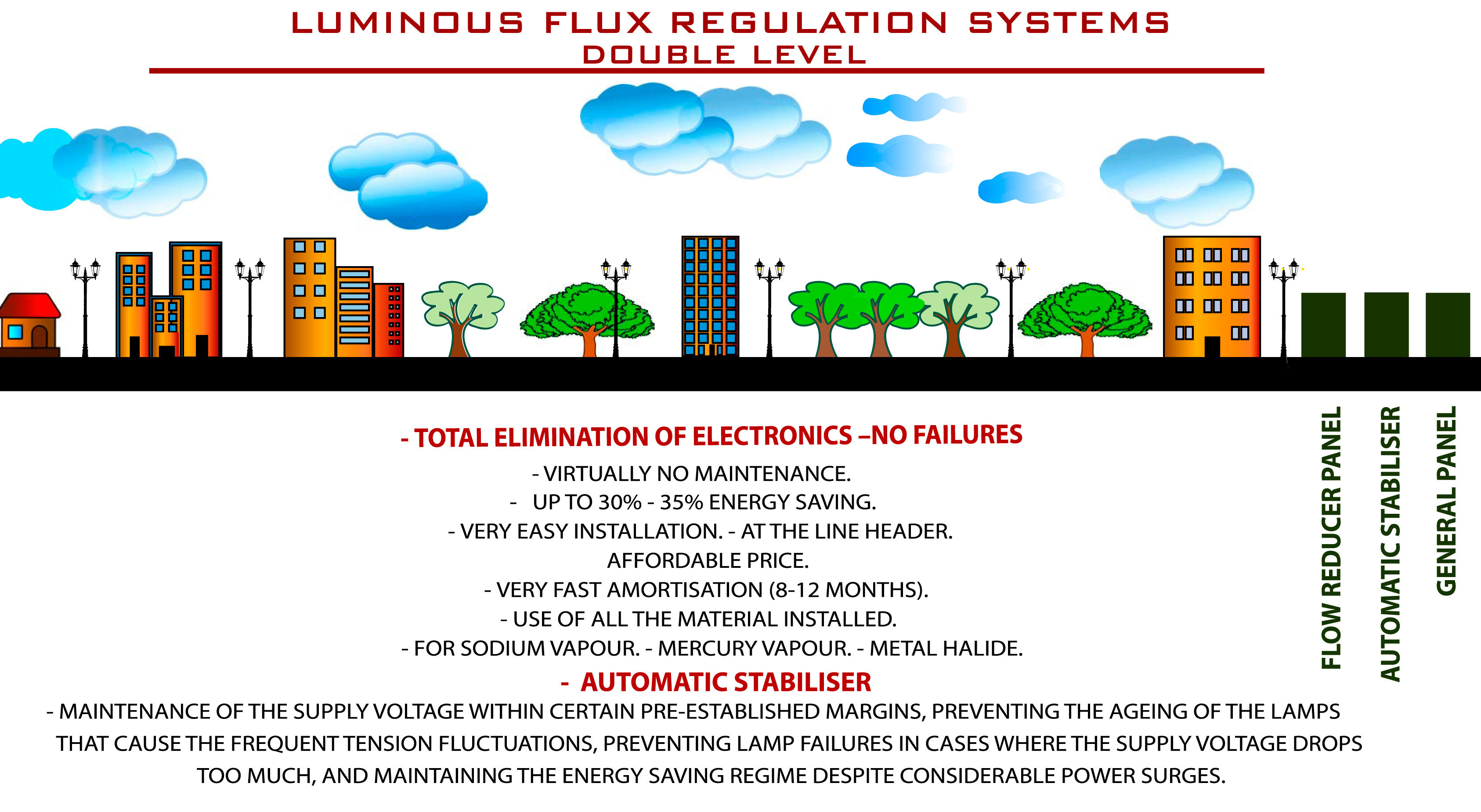
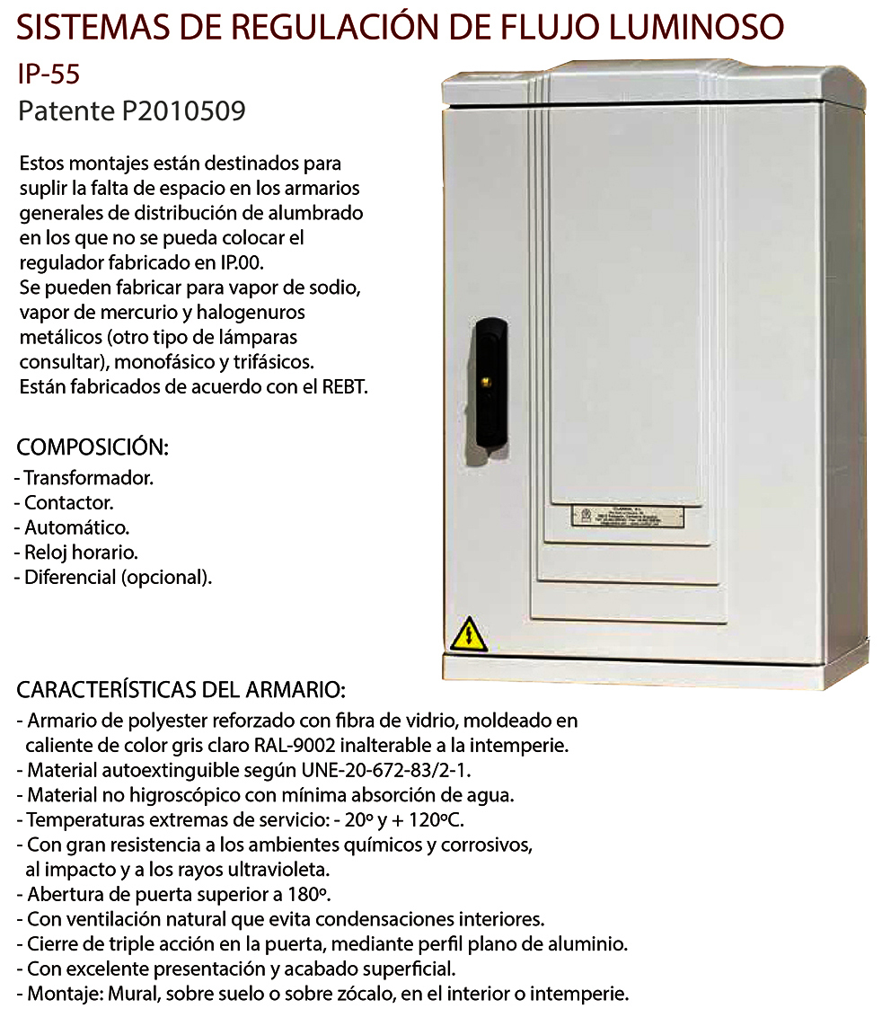
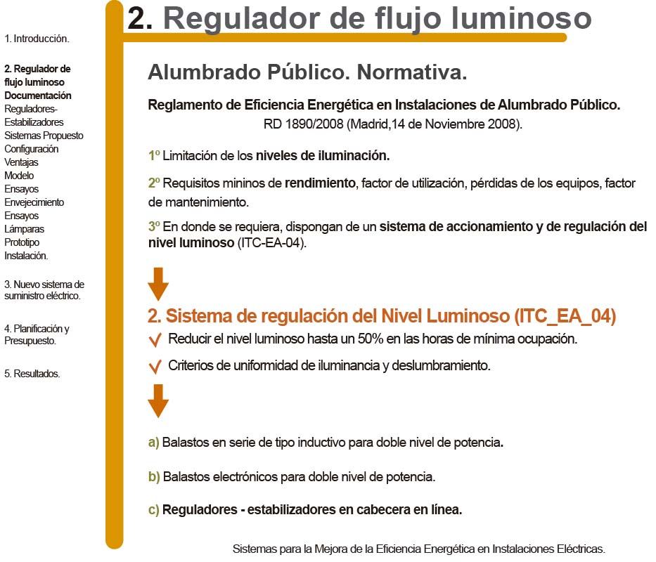
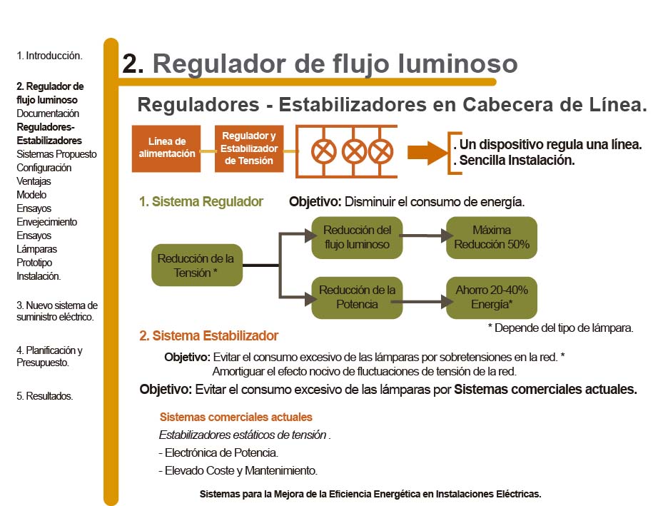
Systems for Regulating Luminous Flux
Patent P2010509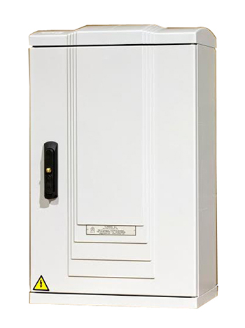 Catalogue
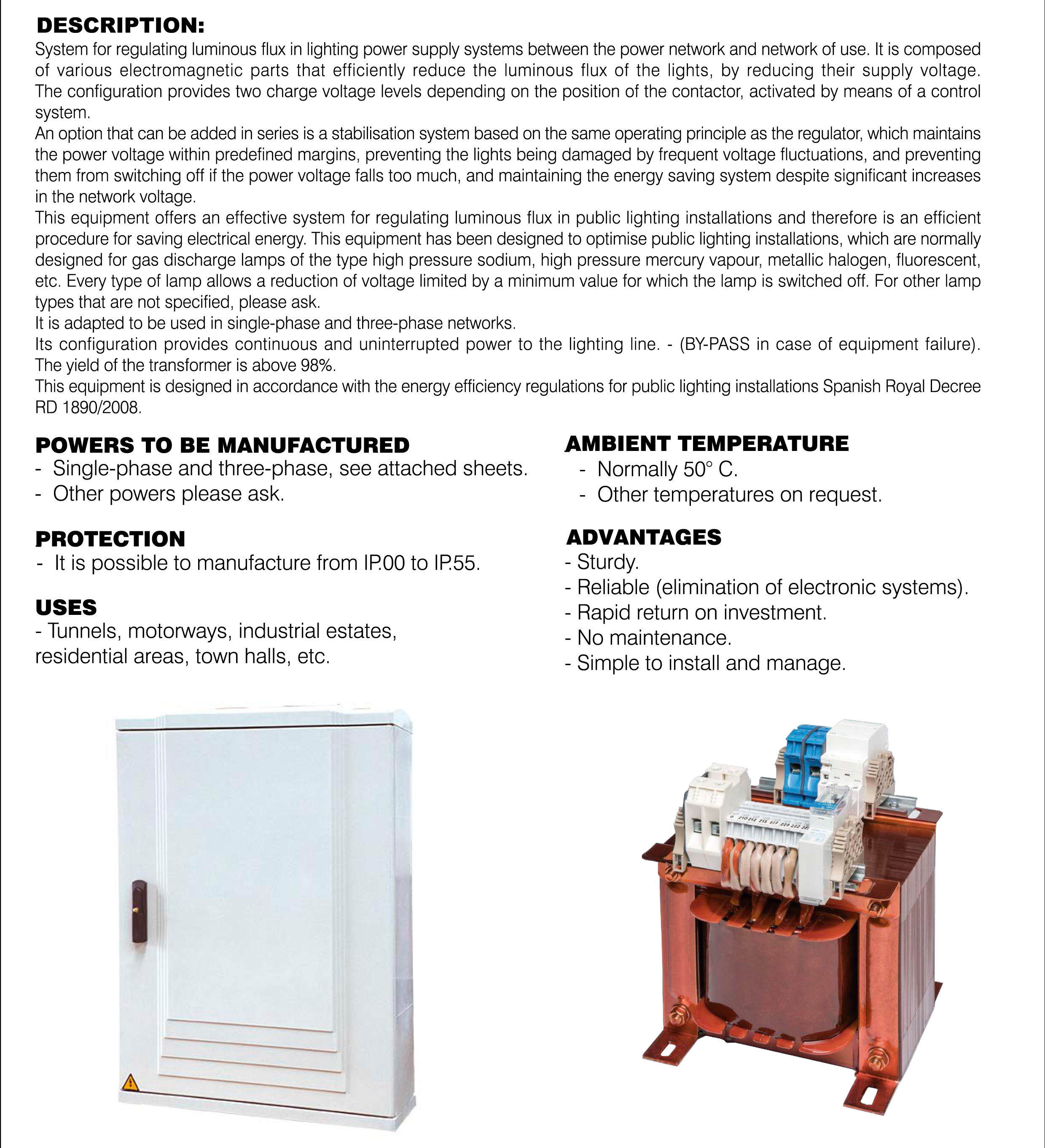
- Three-phase systems
Lighting Flow Regulation Systems.
Patent P2010509Catalogue
 PresentationRoyal Decree 1890/2008 on the regulation of energy efficiency in public lighting installations, defines for this purpose, the application of double lighting levels in outdoor lighting (see page 45995 attached).
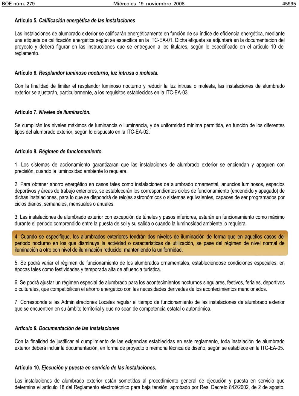
Sodium vapor lamps.
Calculation of savings 10 LAMPS OF 150W SODIUM STEAM
Operation: 8 hours.
1.5 KW x 8 hours = 12kWh (connected to 230 V).
Reducing the supply voltage to 190 V.
The consumption of a sodium lamp at 190 V is approximately 67.5% (saving 32.5%).
12 kWh x 32.5% = 3.9 kWh (per day).
3.9 kWh x 365 days = 1432.5 kWh.
1432.5 kWh x 0.14 € / kWh = 199.29 € annual savings.GraphicsCONSUMED POWER AND INTENSITY OF LUMINOUS FLOW FOR A HIGH PRESSURE SODIUM LAMP
Tests for a 70W lamp.
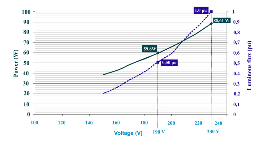
The lamp of 70 W at 230 V consumes 88.61 W, (the additional reactance must be considered) and gives its assigned luminous flux considered 1.0 pu (one per unit 100%).
When the power supply is reduced to 190 V, the luminous flux is reduced by half (0.5 pu). The power consumed at this voltage is 59.8 W, which represents a saving of 32.5%.
Models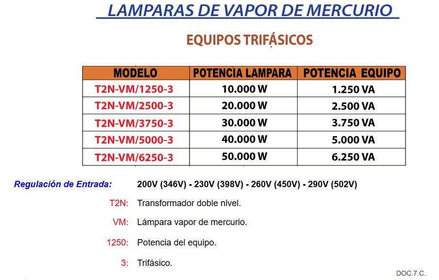
Mercury vapor lamps.
Calculation of savings
10 LAMPS OF 150W MERCURY STEAM
Operation: 8 hours.
1.5 KW x 8 hours = 12kWh (connected to 230 V).
Reducing the supply voltage to 208 V.
The consumption of a mercury lamp at 208 V is about 80% (saving 20%).
12 kWh x 20% = 2.4 kWh (per day).
2.4 kWh x 365 days = 876 kWh.
876 kWh x 0.14 € / kWh = € 122.64 annual savings.
Models
Metal halide lamps.
Calculation of savings Graphics
CONSUMED POWER AND INTENSITY OF LUMINOUS FLOW FOR A METAL HALIDE LAMP
Tests for a 70 W lamp.
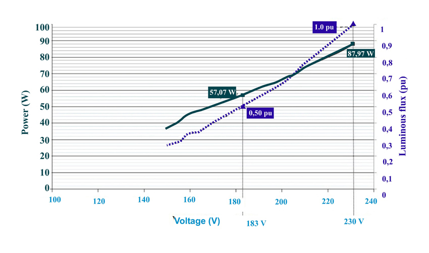
The lamp of 70 W at 230 V consumes 87.97 W, (the additional reactance must be considered) and gives its assigned luminous flux considered 1 pu (one per unit 100%).
When the power is reduced to 183 V, the luminous flux is reduced by half (0.5 pu). The power consumed at this voltage is 57.1 W, which represents a saving of 35.1%.Models
Input Regulation: 230V (398V) – 260V (450V) – 290V (502V) – 310V (537V)
T2N: Double level transformer.
HM: Metal halide lamp.
2446: Power of the team.
3: Three-phase - Oil-immersed


The transformers are manufactured in compliance with IEC 60076-13 and, IEEE C57.1201 (or other required) standards.
The core is made of magnetic sheets with high permeability and low loss rate with a joint assembly of 45º with cooling channels.
All the winding of conductors is made of electrolytic copper of E-CU 99.9%.
Depending on the design of the transformer, the winding can be continuous or with a disk at intervals, with multiple or simple propellers.
The cooling channels are made with properly formed rods and with guide rings.
The derivation occurs in the HV winding, controlled either by a switch or by a bypass transformer.
The windings are autoclaved to reach the exact dimensions and avoid successive failures of lack of elasticity. All the transformer is fitted in the tank and filled with oil in isolation. The tank, normally, is of the vacuum type.
The refrigeration is carried out by means of radiators: mainly bolted, of the removable type; Sometimes it is soldered.
You can use fans or pumps to increase the operation of the transformer.
The transformers are capable of operating at a power greater than the rated power based on the IEC 354 standard.
When the problem of dimensions does not allow to deliver the transformer with the isolated liquid, the tank is carried with inert gas, or the radiators and the conservator are delivered disassembled.
The transformers can be equipped with specific accessories in addition to the standard ones, such as overpressure valve, diaphragm conservator, amperometric transformers, winding temperature indicator, cable box, centralization, etc.
When required, the assembly can be carried out by our specialized personnel.
TECHNICAL CHARACTERISTICS:
RULES
The transformers are made according to IEC 76 standards.
NUCLEUS
It is built with magnetic sheet with oriented crystals, cold rolled and isolated on both sides by means of a thin layer of insulating varnish (Carlyte). The assembly is made with joints interspersed with 45º cuts. The suitably closed assembly ensures a very low noise operation,
ARMOR
In wood or steel bars, according to the construction project, always of adequate dimensions. Vertical holes that allow perfect protection to avoid damage from short circuits.
WRAPPING
In electrolytic copper, isolated with pure cellulose and therefore able to withstand all atmospheric surges. The perfect circulation of the oil, also the interior of the coils, is ensured by means of large channels obtained by means of corrugated and folded cardboard. Before they are assembled, the envelopes are dried and impregnated.
TANK
Structure of welded and reinforced steel, internally painted with varnish indissoluble in the presence of oil and externally corrosion proof. Standard execution with radiators and corrugated steel sheets.
INSULATORS
In dark porcelain, according to the UNEL standard. Easily replaceable when they break.
STANDARD ACCESSORIES
Preserved in oil, oil level indicator, oil filler cap and oil discharge, internal overpressure output device, air dryer connection, thermometer, grounding, loops, rotating slide rollers, switch for regulating high voltage overload .
LOW ORDER ACCESSORIES
High voltage connection boxes, thermometer with electrical contacts, Buccholz relay, sicilagel dryer, switch for regulation of high voltage plugs, auxiliary box.
INSTALLATION
Inside or outside
TESTING
All transformers are tested with routine tests established by the IEC 76 standards. On request, shock wave resistance tests can also be carried out. Special tests to resistance of short circuits.
ELECTRICAL DETAILS, MEASURES, MASS
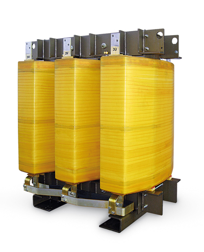
- Cast Resin
Technical Features
STANDARD
The transformers are built in accordance with IEC 726 standards.
CORE
The core is built up of cold rollled oriented grain steel sheet with low specific losses, insulated on both sides by a thin inorganic coating (Carlyte). The sheets composing the core are cut at 45 degrees. Uniform pressing, stiffnes and solidity of the columns assure a low noise level.
MEDIUM VOLTAGE WINDINGS
The high voltage are made of electrolitic aluminium conductors (wire or foil strip depending upon power and voltage requirements). It is possible to produce copper windings. The windings are inglobed under vacuum in class F epoxidic resin. The accuracy of execution of these processes allows the obtainement of windings free from partial discharges.
LOW VOLTAGE WINDINGS
The low voltage windings are made of strip or foil (copper or aluminium conductor depending upon power and voltage requirements). Class H insulating material is used.
STANDARD ACCESSORIES
Skid under base or truck with bidirectional wheels; Lifting lugs; Earthing terminal.
OPTIONAL ACCESSORIES
Thermometer dial type whith electric contacts; Temperature monitoring unit without display; Temperature monitoring unit with display; Cubicle IP 315 or other; Forced ventilation system.
TEST
All transformers are singulary tested with routine test, according to standard IEC 726. Upon request the following type test can be carried out; temperature.
Detalles y Medidas

- PHASE MOTOR STARTING TRANSFORMERS
- Transformers and Three-Phase Autotransformers from 0.5 to 5,000 KVA. low voltage and dry.
1.1. Construction features
CLARKIA transformers have been designed and manufactured strictly in accordance with standards IEC 60076-6.
Coils:
Coiling is made of copper class H-Grade 2/thermal class H.200, according to IEC 60317-3.
Insulation varnish for this copper is a polyester-IMIDA modified THEIC with a polyamide-IMIDA overcoat. This kind of winding wires are homologated according to UL-E103536 (NEMA MW-35C).
All our coils lack insulation boards, which makes them very reliable for humidity in tropical and marine climates, etc…
Insulation is achieved through fiberglass separators class F.
Coils have been designed and manufactured for use in a room temperature of 45ºC with insulations class F (155ºC) and a class B temperature increase (70ºC), always considering the continuous operation.
Optionally, copper strips can be also used.
All coils can carry additional regulation intakes +2,5%, -2,5%, +5%, -5%,etc… upon customer request.Core:
We work with the best qualities of magnetic mat, supplied by the world’s leading manufacturers (ThyssenKrupp, f.e.).
Dimensional tolerances of materials fall within standard DIN 41.302 (Part 1).
Also magnetic properties of materials fall within standards EN 10106 and EN 10107.
All magnetic mats comply with REACH and RoHS regulations.Varnishing:
Each unit is carefully varnished with anti-flash alquidic varnish.
Once mature, the product complies with the following international standards: BS 5629: TYPE 1.1 (CEI 85) with class F insulation.
A fungicide comes standard, which provides total protection class 0 (no growing) according to standard BS 3900 PTG 6, an additional characteristic suitable for tropicalization and using in warm, humid climates.Metal casing:
Casing is manufactured with steel plates, 1,5. mm thick. Firstly, it is subjected to degreasing and pickling and subsequently a 70-90 microns layer of epoxy polyester powder coating is applied in furnace.
Protection of the box is IP23 (other protections available upon request)
Paint color is RAL 7035 (other colors available upon request)– Our manufacturing is backed by a quality assurance system based on the ISO 9001 standard.
– All units are tested unitarily and shipped with their corresponding test certificate in accordance with IEC 60076.3PH TRANSFORMER 1000 KVA 440/220 V – 50 Hz
POWER RANGE THREE-PHASE TRANSFORMERS 0,5 / 10 / 15 / 20 / 25 / 30 / 40 / 50 / 60 / 70 / 80 / 90 / 100 / 125 / 150 / 200 / 250 / 300 / 400 / 500 / 750 / 1000 / 1500 / 2000 / 2500 / 3000 / 4000 / 5000 KVA.
POWER RANGE THREE-PHASE AUTOTRANSFORMERS 5 / 10 / 15 / 20 / 25 / 30 / 40 / 50 / 60 / 70 / 80 / 90 / 100 / 125 / 200 / 250 / 300 /400/500 / 750 / 1000/ 1250/ 1500 / 1750 / 2000 / 2500 / 3000 / 4000 / 5000 KVA. – FOR HIGHER OR LOWER POWERS, PLEASE CONSULT
VOLTAGE RANGE TRANSFORMERS PRIMARIO SECUNDARIO 115/220/380/400/440/660/690 V. 115/220/380/400/440/660/690 V. VOLTAGE RANGE AUTOTRANSFORMER 115/220/380/400/440/660/690 V. – WE CAN MANUFACTURE WITH THE INPUT/OUTPUT VOLTAGE REQUIERED BY THE CLIENT
– FREQUENCY 50/60/400 Hz– ALL OUR MANUFACTURES ARE SUPPORTED BY A QUALITY GUARANTEE SYSTEM BASED
ON THE STANDARD ISO 9001– ALL UNITS ARE TESTED UNITARILY AND SENT WITH THEIR CORRESPONDING TEST CERTIFICATE, ACCORDING TO IEC 60076
VDE symbolsDVector diag.Conection schem.CEI
symbolsComm. grp.Sub-grp.H.T.L.T.H.T.L.T.AA1
 Dd0A2
Dd0A2
 Yy0A3
Yy0A3
 Dz0BB1
 Dd6B2
Dd6B2 Yy6B3
Yy6B3
 Dz6CC1
 Dy5C2
Dy5C2 Yd5C3
Yd5C3
 Yz5DD1
 Dy11D2
 Yd11D3
 Yz11
Yz11
Tel: (34)-942 269 363 - | e-mail: clk@clarkia.net